How to Calculate the size of Water Pipes for Buildings
Water always flows downhill.
This is the same a saying water always flows from a point of higher water level to a point of lower water level.
Which is the same as saying water always flows from a point of higher pressure to a point of lower pressure.
There are no exceptions to this rule. Even when pumping.
A pump simply raises the water pressure/level at the pump to a pressure/level above the point that is being pumped to, and the water flows downhill from there.
Therefore, if water is always flowing downhill, there must be a slope or grade of this so-called hill.
Well, there is, and its called the Hydraulic Grade. So, if we know the hydraulic grade, and how much water we want to deliver, we can use a formula to determine what size pipe we will need.
It works like this, the steeper the grade the faster the flow, just like anything rolling down a hill.
The bigger the pipe, the more flow, that's pretty obvious. So putting it all together, if we flatten the grade, we must increase the pipe size to get the same flow. Conversely a steeper grade requires a smaller pipe size for the same flow.
A slope or grade can be defined by a horizontal length and a vertical drop.
For example 1 in 100 (or 1:100) means 1 measurement unit vertical to 100 same measurement units horizontal.
Therefore to start calculating pipe sizes we must first find a length and a vertical drop
To make life easier, the Plumbing Codes start out by calculating a length called the "Index Length".
The "Index length" is typically the length of pipe to the hydraulic worst case. The hydraulic worst case is the plumbing fixture that will have the lowest (worst) pressure when the building is in use. The worst case is usually the furthermost fixture from the street water main (or other water source). However for high rise buildings it could be the highest fixture.
So we now have a length, if we had a height we could work out a grade could we not? Turns out we do have a height. Like any hill it is the difference between the top and the bottom. The top water level and the bottom water level.
The top water lever relates to the street pressure, and the bottom water level relates to our desired pressure at the end fixture and the difference in height between the street and the end fixture.
All we need now is the design flow, and we have enough info for our formula.
The plumbing Codes give us the design flow, and the formula.
So, Hydraulic Grade, design flow, formula, gives pipe size.
The Code Method.
The method involves calculating the Hydraulic Grade required to get enough pressure to this 'worst case' fixture.
Once this Hydraulic Grade has been calculated, all water pipes in the project are designed with this grade.
The theory being, that if sufficient pressure can be delivered to the 'worst' case, then all other plumbing outlets in the system should have a better pressure.
In short, all fixtures in the building will have sufficient pressure.
This method is suitable for domestic and commercial plumbing systems.
However not recommended for systems that must produce a pressure within a certain range, as in fire systems.
Municipal systems and large networks are also designed differently.
One other thing, as water travels along a pipe it looses pressure due to friction with the pipe walls.
This is the same as loosing water level/height. Going back to our hill analogy, our hill is not so high anymore if some of the height has disappeared, or been lost.
So the grade is flatter. A flatter grade means a slower flow. A Slower flow needs a bigger pipe to deliver the required design flow.
As can be seen, pipe friction is very important in calculating the pipe size.
There are two types of friction, friction with the pipe walls, and friction by changes in direction or diameter, (bends and fittings). Pipe friction is allowed for by the pipe flow formula. Friction of bends and fittings is accounted for by giving the pipe an extra length that will have the same amount of friction as the bends and fittings. This is called the 'equivalent' length. So instead of varying the height of our slope by calculating the pressure loss of each fitting, we make the length longer by adding the equivalent length. This has the same effect. It makes the grade flatter, and is a lot easier to calculate. More detail on this below.
The Design Flow
OMG! the flow can be anything from zero in the middle of the night to having all taps turned on at once. So how do we arrive at a "design" flow. Fortunately the Plumbing Codes allocate a number to each fixture, called a 'loading unit' (LU) or a 'fixture unit'(FU). This number started out as gals/min (or something) but over the years this number has been tweaked and also takes into account a likely frequency of use. These numbers are added up along the pipeline as each fixture is added, and a formula (or graph) in the Plumbing Code derives the 'Probable Simultaneous Flow' at that point.
If there is only one fixture, then the pipe must be sized for 100% of this flow requirement. However as the number of 'Loading Units' builds up, it becomes less likely that all fixtures will be operating at the same time. So as the number of LU's increase, the likely percentage of fixtures operating at any one time decreases. (to a certain minimum)
So, the Plumbing Code will give the loading units to be used for each fixture, and a table, formula, or graph to find the Probable Simultaneous Flow associated with the number of fixtures serviced.
Surprisingly the Worlds Plumbing Codes differ in the LU's given to each fixture, and also the Probable Simultaneous Flow. But as they each have slightly different formulas and design methods, the end pipe size may be very similar. Check out the comparison Here.
Pressure
Pressure in a pipeline is governed by the height of the supply reservoir. (or pressure supplied by a pump). The higher the reservoir above the building, the greater the pressure at the building.
Street main pressure can also vary during the day. The minimum supply pressure must be used.
This minimum pressure can be obtained from the Water Utility, or by direct measurement at peak flow times.
It is easier to understand pipe size calculations if we think of pressure in terms of water level, or height of water, this is called 'head' of water. Psi and kPa are the pressures due to that height/weight of water.
For instance 100 feet head = 43.3psi; 30.5m head = 300kPa (approx). Similarly with a pump, it is easier to think that a pump will pump water to a certain height, and it will flow downhill (gravitate) from there.
If a vertical pipe was connected to a water main, the water would rise to a certain height. This height of water above the water main is the 'head' of water. The weight of which is the pressure.
The water in this case will not rise higher than the water level in the reservoir, or the height supplied by the pump. If it did, water would be flowing the other way, into the reservoir and not out. Remember that water must always flow down hill.
From a point of higher pressure to a point of lower pressure, from a high water level to a lower water level etc.
If we were to put a series of vertical pipes along a water main and draw a line between the top water level in each pipe, this line would be called the Hydraulic Grade line. This is what the Hydraulic Grade line represents. The height to which the water would rise at each point in the system. In other words the 'Head' at each point along the pipeline.
If water is flowing, pressure/head is being lost due to friction, therefore the height to which water will rise is getting progressively lower along the pipe line. So the hydraulic grade line is always falling (when water is flowing). If there is no flow there is no head loss due to friction, and the Hydraulic grade line will be horizontal.
A pressure pipe is obviously a pipe flowing under pressure as in water pipes. A gravity pipe is a pipe that flows without pressure as in sanitary drainage, and storm water pipes. If a gravity pipe is flowing full, we use the same formula as a pressure pipe, using the 'hydraulic' grade for the pressure pipe, and the actual grade for the gravity pipe.
The Plumbing Codes set a maximum and a minimum pressure. The maximum is around about 500-550kPa (80psi). Pressures above this require a pressure reducing valve. The minimum is the pressure required to operate the fixture in question. The codes have recommendations on this. This is called the 'Residual Head'.
Residual Head
This is the pressure that is considered the lowest necessary to satisfactorily work the particular fixture. This can vary between fixtures, eg a mixing valve needs more pressure than a standard faucet (tap). Some Codes stipulate the required residual head for each fixture, other codes take the worst case.
Plumbing Codes stipulate anywhere from 5 to 14m. (7 to 20 psi) sometimes even more for special fittings.
Manufacturers recommend a minimum of 11m (16 psi) for most mixing and tempering valves. The Uniform Plumbing Code used in the United States also uses approximately this figure.
The free versions of the program use 15m (approx 150 kPa) as the residual head for Australia. And 14m (20 psi) for the international versions.
Note: The Australian Plumbing Code AS/NZS 3500 allows 5m; but with the advent of mixing valves etc this is rumored to be be increased in line with International standards, and Manufacturers recommendations.
The pro version allows the user to enter any value.
Water will always flow from a point of higher head (pressure) to a point of lower head (pressure) even if the difference is only mm's. It may not flow very fast under these conditions, (a flat hydraulic grade) but it will flow.
So in the case of a rain water tank flowing to a kitchen sink only, a very low residual head may be acceptable to the user. BTW those offices with replaceable drinking water containers have a head equivalent to the depth of water in the bottle.
Pipe Friction
Friction within pipes and fittings cause loss of head (pressure). Friction is dependent on the velocity of the flow, the faster the flow the more friction. All pipe flow formulas have some sort of friction factor that allows for pipe roughness. Each type, or condition of pipe will have a different factor. BTW Google will tell you the pipe formulas, and the friction factors to use with that particular formula.
A smooth pipe like copper or plastic can carry more water than a rough pipe like concrete or rusted cast iron.
Friction in Bends and fittings
Friction in bends and fittings can be calculated by two different means :-
It is impossible to predict the exact number of bends and fittings a plumber may use on small pipe lines. Different plumbers may plumb the same job differently. They may use different methods to avoid obstructions etc. One plumber may use 2*45 deg bends instead of 1*90 deg bend just because he has them with him.
All this makes a difference.
Plus it is a big job to count all possible bends and fittings.
So to make life easier the Plumbing codes prefer to start with the equivalent length method.
Simply increase the actual length by 50% to allow for the unknown number of bends and fittings.
The free versions of the pipe sizing programs use this approach.
The Australian Plumbing Code uses this method, other Plumbing Codes use this method as a first trial.
Is using the 'Equivalent Length' guess method any good?
Head loss in fittings depends on the water velocity. The faster water flows, the more friction, therefore more head loss.
As a comparison lets work out the head loss by both methods. The minor loss coefficient method, and the Equivalent length method. The formula for the minor loss coefficient method is,
Where:-
head loss is in metres (or feet)
k = head loss factor (minor loss coefficient) for fittings and valves.
V = Velocity in metres/sec (or feet/sec)
g = acceleration due to gravity 9.81m/s/s (or 32 feet/s/s)
The important thing is that each fitting is allotted a 'k' value (called head loss coefficient, or minor loss coefficient).
These vary according to the pipe size, however some average values are shown below. For example:-
Lets say the length to the furthermost fixture in a typical building is about 30m (100 feet), and the pipe is flowing at the maximum allowable velocity of say 2.4m/s (8 ft/sec).
This would equate to a 20mm (3/4") flowing at 0.55 L/s (8.7 gal/min).
Note: The actual internal diameter (ID) of this (copper) pipe is about 17mm. Say we have: 1x7(one water meter) + 2 x 0.2 (Gate valve) + 2 x 1.75 (Tees) + 6 x 1.2 (Bends), giving a total k about 18.
Head loss through 30m of 20mm (actual ID is 17mm) @ 2.4m/s, 0.55 L/s = 13m,
(100 ft, 3/4" (0.67" I.D.), V=8 ft/s, Q=8.7 galUS/min, HL = 43 ft)
Therefore allowing 50% seems a good figure.
This means that:-
Using the Equivalent Length method
As can be seen, increasing the pipe length by 50% is as good an estimation as any. Bear in mind that everything is an estimation, including the design flow. So no point in splitting hairs at this stage.
In practice however, these head losses will tend to average out, some sections will be over estimated and some pipe sections will be under estimated.
Pipe friction Formulas
There are a lot of standard formulas that calculate flow in pipes eg Manning, Colebrooke white, Darcy, Hazen Williams etc. Friction is accounted for by using a pipe material 'roughness coefficient' in the formulas. However all formulas give a similar result. These programs apply the formula used in the relevant Plumbing Code.
In our situation we start with an 'estimated' flow, we've made a 'best guess' allowance for friction losses in bends and fittings by increasing the length by 50%, Then we normally choose a pipe that is a few mm bigger than necessary, because that is the nearest available size.
Also a large percentage of the pipes will be controlled by velocity (not pressure) more on this below. So no real point in agonizing too much over the formulas, or the head loss, when all the major input parameters can, and do, vary.
However you will find that these programs give the same result as the respective plumbing Codes.
Hydraulic Grade to Furthermost or Highest fixture (Worst case)
As I said, water always flows 'downhill'. The Hydraulic Grade is the slope of that hill. The 'Hydraulic Grade Line' (HGL) is a graphical representation of the hydraulic grade. (refer below) The X-axis represents the length of pipe, and the Y-axis represents the height to which water will rise at all points in the pipe section.
If we draw a vertical line from any point along the pipeline to the Hydraulic Grade Line, the length of this line represents the head/pressure at that point.
The Hydraulic Grade involves only four things:-

Now lets look at the diagram. The available head is what we need to calculate the Hydraulic grade.
The available head is the head that is available for friction losses.
If this head is divided by the 'equivalent' length, we have the hydraulic grade that can be used in our pipe flow formulas.
The steeper the grade the more flow in the pipe. Knowing the Hydraulic grade, and the design flow, we use the Code formula (or any pipe flow formula) to calculate the water pipe size.
Plumbing Code formulas are usually some variant of the 'Hazen Williams' formula.
Note: in real life the hydraulic grade is not a straight line unless the pipe is straight, and the size or flow do not change along the length of the pipeline.
Any head loss as in bends and fittings, will introduce a vertical drop in the line, and changes in size or flow will change the grade of the line.
Smaller pipes or larger flows require a steeper grade, as there is more friction loss.
Conversely larger pipes and/or less flow make the line flatter.
Pipes
Pipes come in many different materials, diameters, and strength grades. To make life easier, pipes are given a 'nominal' diameter. So a 1 inch (25mm) pipe in copper will actually have a different inside diameter for all strength grades, a 1 inch pipe in plastic will have a different diameter again for all the different types of plastic and strength grades. But they are all refereed to as a 1 inch or 25mm dia pipe when purchasing. Sometimes you will see this expressed as DN (diameter nominal).
Pipe flow formulas only relate to the inside diameter (ID).
So the pipe sizing programs on this site calculate the actual inside diameter, and if this exact size does not exist, then for the Australian Programs the next larger available size is chosen. The nominal diameter associated with this size is then displayed.
The international versions display the actual inside pipe diameter (I.D.)
The user can then select the nearest available (larger) pipe size from the Manufacturers data of the material and strength class of choice.
Maximum Allowable Velocity
The worlds Major Plumbing codes set a limit to the maximum water velocity in a pipe.
There are three reasons for setting the maximum allowable velocity.
The Proversions allow the user to enter any value. It is not recommended to increase the velocity above 3m/s. However sometimes it may be advantageous. For example underground pipes of straight runs with no bends or fittings, especially valves. Hence it may be justified in irrigation, fire flows, etc, or even in areas of high pressure when the dwelling is a long way from the source.
But this will be outside the plumbing codes.
Lowering the velocity on the other hand, would be advantageous.
Lowering the allowable velocity requires a larger pipe to get the same flow. Increasing the allowable velocity reduces the pipe size.
So how does this work in practice? The maximum velocity limitation occurs when the available water pressure is high enough to push the design flow of water at a high velocity through a small pipe, and still satisfy the residual pressure requirement at the far end. So to slow the velocity down to the required maximum, the pipe size must be increased. (A bigger pipe carries the same flow at a slower rate.)
As friction loss is dependent on velocity, the friction loss is also reduced. So we have increased the pipe size bigger than what is theoretically required, thereby reducing the friction loss. If we don't loose as much friction as we originally allowed for, we end up with more pressure at the worst case than we originally allowed for. Which can only be a good thing. Some Codes, to be strictly correct, will compensate for this somewhere else in the piping system.
The difficult and laborious way to size pipelines is to progressively calculate the head loss in every individual pipe.
The object is to adjust all the friction/head loss in each pipe section so that the total head loss is as close as possible to the 'available head loss' as shown in the diagram above.
This is necessary in systems where the end pressure must fall within certain limits, as in fire systems, and is recommended in certain plumbing codes. Usually involves a lot of trial and error.
Is it necessary to recalculate the start pressure at the riser for every level of a high rise building?
And will this change the pipe sizes on each level, even if the Architecture is identical?
And is it even worth thinking about?
Well, the lower levels usually have so much pressure that the pipe size is velocity controlled, so recalculating the start pressure will not effect the pipe size anyway. Also during construction it is always better to keep things consistent. Every floor plumbed the same. Easier and quicker to estimate and build, and less chance of mistakes during construction.
Code Differences
Now that we know a few things we can check out the differences in the Worlds major Plumbing Codes.
The Australian Code has a 'Probable Simultaneous flow' of approximately half that of the International Plumbing Code, the British Code BS6700, and the Uniform Plumbing Code (USA).
Does this mean that the Aussies don't shower as much as the rest of the world? or do they have more flow restricting devices?
The Brits however have now introduced a new code BS EN 806 which supersedes BS 6700. This code now beats the Aussi code in that the probable simultaneous design flow is even less. Testing of actual flows are less again.
Well lets take a closer look.
To compare apples with apples I have used a typical residence of:-
1 Kitchen consisting of sink, and dishwasher.
2 Bathrooms consisting of shower, toilet and hand basin
1 laundry consisting of washing machine, and tub.
and one garden hose.
The International Plumbing Code allows grouping of bathroom fixtures. That is, the total loading units of the group is less than the sum of the individual fixtures. This substantially reduces the total loading units, and puts it exactly in line with the old British Standard BS 6700.
The Aussie Code has a one size fits all approach, which significantly reduces the design time, but produces a larger pipe size. However the end result may be similar.
Lets see how this works:-
Australian Plumbing Code
All pipe lines in the project are sized to the same hydraulic grade. That is, the hydraulic grade to the worst case. The end flow capacity increases because pipes are not manufactured in the exact calculated size, and a pipe size larger than the theoretical is required. The end flow capacity also increases if the maximum velocity limitation has required a larger pipe size. This increase in capacity is not compensated for elsewhere in the pipe design.
However, for the other codes, there is a larger flow requirement, but also constant manipulation of the pipe size to follow as closely as possible to the design flow.
Below is an attempt to demonstrate graphically how this works.
This diagram is not strictly correct, but drawn this way only to demonstrate the point.
International Plumbing Code
The hydraulic grade is recalculated for each section to try and finish as close as possible to the required end pressure.
If we want to do things the hard way we count all the bends and fittings, and all the other head losses, then calculate the head loss in each pipe section, sum all the head losses and try to make this figure as close as possible to the 'available' head loss.
This is fine, but all the head losses are dependent on the flow velocity, which is dependent on the pipe size. WHICH IS WHAT WE ARE TRYING TO FIND OUT!
So we start with a guess of the pipe size for each pipe section, and then use trial and error to end up with a total head loss, that is as close as possible to what is available for friction.
The end result is, we may or may not have succeeded in reducing a couple of pipe sizes. But are we any more correct? Given that it is impossible to accurately predict the number of bends and fittings the plumber will use, and the 'design' flow may or may not occur.
Is there such a thing as over design in plumbing, (or is it just a better design) if increasing the pipe size reduces the pressure fluctuations?
The free International version of these programs uses the simple approach.
Pro Version
The Australian Proversion will calculate pipe sizes up to 200mm.
The Pro-versions allow the user to input the number of individual fixtures. Also allows the user to input known flows and loading/fixture units.
The Proversion allows the user to change the maximum allowable velocity. This is useful for some other plumbing standards, or for heated water, or for some 5 star hotels that specify different velocities for different locations in the building.
Also allows the user to change the minimum residual head. Handy for tanks (lower residual head), fire hose reels or hydrants (higher residual head), or other fixtures where the manufacturer requires a different minimum head for proper operation eg mixing valves.
The Australian Proversion also has a table that displays the capability of every pipe size, for the calculated Hydraulic Grade.
That is :-
For example, it might show that a DN25 copper tube can adequately service 3 dwellings, and the next size up (32dia) can service 8 dwellings. So no need to calculate the pipe size for all the dwellings from 3 to 8, as the answer will be 32mm dia.
Also, showing the flow capacity of each size will help in cases where the flow is known. For example, irrigation, some fire services, and some mechanical systems.
If the velocity shown is the maximum allowable, then we know that velocity is controlling the pipe size, not the pressure.
Which means that we have plenty of pressure, which in-turn suggests that we should end up with more pressure at the end point than our desired minimum.
Pumps
Pro version also calculates Pump Duty. This is the required operating point of the pump. It is the flow required, and the pressure required at that flow.
If the hydraulic grade falls below 1:33 then a pump size is calculated. With this hydraulic grade a single residence will require around a DN32 (1.25 inch) pipe. So better to put on a small pump. This is also useful when pumping from tanks etc where the start pressure is zero, or it could be less than zero (less than atmospheric) if the pump is above the tank.
The user can also change this hydraulic grade to change pipe sizes and pump head.
However if the pump is above the tank water level, the program limits the start pressure able to be entered to -60kPa ( negative 6m). Centrifugal pumps will be struggling to suck that high.
However to allow for the head loss of valves, bends and fittings etc, it may be advisable to limit the suction height to about 3m.
When sucking with a pump, is is also necessary to check the NPSH (net positive suction head) of the pump with the Manufacturer. For instance, atmospheric pressure is about 10m (approx 100kPa) (34 feet), but this is already allowed for on our pressure gauge when it reads zero.
So when we read the pressure in a water main, we are reading the pressure above atmospheric.
If we put a pressure gauge on a vacuum it would read -10m (approx -100kPa).
However when sucking, the pump needs to know the pressure above a vacuum. That is the NPSH.
So if a vacuum is -10m and we are only sucking -6m of that, the remainder is 10-6 = 4m. This is the NPSH.
For the phone version, When the pump duty is calculated, use the pump kPa (or start) pressure, (shown at the end of the page) as the 'Start pressure' to calculate the pipe sizes.
For the PC version this is automatic, and the pump calculations are more detailed.
The pump 'duty' point is not the figure that the local pump suppliers usually quote. The suppliers normally quote the maximum pressure that the pump can supply (at no flow). The Duty Point is the required pump pressure when the pump is operating at the 'design' flow. For centrifugal pumps (which is mainly what is used in plumbing situations) the pressure falls off with increasing flow. However somewhere in the system the manufacturer, or pump supplier, will have a 'Pump Curve' that shows pump pressure associated will all flows the pump can produce. Check that out to get the correct pump.
Water always flows downhill.
This is the same a saying water always flows from a point of higher water level to a point of lower water level.
Which is the same as saying water always flows from a point of higher pressure to a point of lower pressure.
There are no exceptions to this rule. Even when pumping.
A pump simply raises the water pressure/level at the pump to a pressure/level above the point that is being pumped to, and the water flows downhill from there.
Therefore, if water is always flowing downhill, there must be a slope or grade of this so-called hill.
Well, there is, and its called the Hydraulic Grade. So, if we know the hydraulic grade, and how much water we want to deliver, we can use a formula to determine what size pipe we will need.
It works like this, the steeper the grade the faster the flow, just like anything rolling down a hill.
The bigger the pipe, the more flow, that's pretty obvious. So putting it all together, if we flatten the grade, we must increase the pipe size to get the same flow. Conversely a steeper grade requires a smaller pipe size for the same flow.
A slope or grade can be defined by a horizontal length and a vertical drop.
For example 1 in 100 (or 1:100) means 1 measurement unit vertical to 100 same measurement units horizontal.
Therefore to start calculating pipe sizes we must first find a length and a vertical drop
To make life easier, the Plumbing Codes start out by calculating a length called the "Index Length".
The "Index length" is typically the length of pipe to the hydraulic worst case. The hydraulic worst case is the plumbing fixture that will have the lowest (worst) pressure when the building is in use. The worst case is usually the furthermost fixture from the street water main (or other water source). However for high rise buildings it could be the highest fixture.
So we now have a length, if we had a height we could work out a grade could we not? Turns out we do have a height. Like any hill it is the difference between the top and the bottom. The top water level and the bottom water level.
The top water lever relates to the street pressure, and the bottom water level relates to our desired pressure at the end fixture and the difference in height between the street and the end fixture.
All we need now is the design flow, and we have enough info for our formula.
The plumbing Codes give us the design flow, and the formula.
So, Hydraulic Grade, design flow, formula, gives pipe size.
The Code Method.
The method involves calculating the Hydraulic Grade required to get enough pressure to this 'worst case' fixture.
Once this Hydraulic Grade has been calculated, all water pipes in the project are designed with this grade.
The theory being, that if sufficient pressure can be delivered to the 'worst' case, then all other plumbing outlets in the system should have a better pressure.
In short, all fixtures in the building will have sufficient pressure.
This method is suitable for domestic and commercial plumbing systems.
However not recommended for systems that must produce a pressure within a certain range, as in fire systems.
Municipal systems and large networks are also designed differently.
One other thing, as water travels along a pipe it looses pressure due to friction with the pipe walls.
This is the same as loosing water level/height. Going back to our hill analogy, our hill is not so high anymore if some of the height has disappeared, or been lost.
So the grade is flatter. A flatter grade means a slower flow. A Slower flow needs a bigger pipe to deliver the required design flow.
As can be seen, pipe friction is very important in calculating the pipe size.
There are two types of friction, friction with the pipe walls, and friction by changes in direction or diameter, (bends and fittings). Pipe friction is allowed for by the pipe flow formula. Friction of bends and fittings is accounted for by giving the pipe an extra length that will have the same amount of friction as the bends and fittings. This is called the 'equivalent' length. So instead of varying the height of our slope by calculating the pressure loss of each fitting, we make the length longer by adding the equivalent length. This has the same effect. It makes the grade flatter, and is a lot easier to calculate. More detail on this below.
The Design Flow
OMG! the flow can be anything from zero in the middle of the night to having all taps turned on at once. So how do we arrive at a "design" flow. Fortunately the Plumbing Codes allocate a number to each fixture, called a 'loading unit' (LU) or a 'fixture unit'(FU). This number started out as gals/min (or something) but over the years this number has been tweaked and also takes into account a likely frequency of use. These numbers are added up along the pipeline as each fixture is added, and a formula (or graph) in the Plumbing Code derives the 'Probable Simultaneous Flow' at that point.
If there is only one fixture, then the pipe must be sized for 100% of this flow requirement. However as the number of 'Loading Units' builds up, it becomes less likely that all fixtures will be operating at the same time. So as the number of LU's increase, the likely percentage of fixtures operating at any one time decreases. (to a certain minimum)
So, the Plumbing Code will give the loading units to be used for each fixture, and a table, formula, or graph to find the Probable Simultaneous Flow associated with the number of fixtures serviced.
Surprisingly the Worlds Plumbing Codes differ in the LU's given to each fixture, and also the Probable Simultaneous Flow. But as they each have slightly different formulas and design methods, the end pipe size may be very similar. Check out the comparison Here.
Pressure
Pressure in a pipeline is governed by the height of the supply reservoir. (or pressure supplied by a pump). The higher the reservoir above the building, the greater the pressure at the building.
Street main pressure can also vary during the day. The minimum supply pressure must be used.
This minimum pressure can be obtained from the Water Utility, or by direct measurement at peak flow times.
It is easier to understand pipe size calculations if we think of pressure in terms of water level, or height of water, this is called 'head' of water. Psi and kPa are the pressures due to that height/weight of water.
For instance 100 feet head = 43.3psi; 30.5m head = 300kPa (approx). Similarly with a pump, it is easier to think that a pump will pump water to a certain height, and it will flow downhill (gravitate) from there.
If a vertical pipe was connected to a water main, the water would rise to a certain height. This height of water above the water main is the 'head' of water. The weight of which is the pressure.
The water in this case will not rise higher than the water level in the reservoir, or the height supplied by the pump. If it did, water would be flowing the other way, into the reservoir and not out. Remember that water must always flow down hill.
From a point of higher pressure to a point of lower pressure, from a high water level to a lower water level etc.
If we were to put a series of vertical pipes along a water main and draw a line between the top water level in each pipe, this line would be called the Hydraulic Grade line. This is what the Hydraulic Grade line represents. The height to which the water would rise at each point in the system. In other words the 'Head' at each point along the pipeline.
If water is flowing, pressure/head is being lost due to friction, therefore the height to which water will rise is getting progressively lower along the pipe line. So the hydraulic grade line is always falling (when water is flowing). If there is no flow there is no head loss due to friction, and the Hydraulic grade line will be horizontal.
A pressure pipe is obviously a pipe flowing under pressure as in water pipes. A gravity pipe is a pipe that flows without pressure as in sanitary drainage, and storm water pipes. If a gravity pipe is flowing full, we use the same formula as a pressure pipe, using the 'hydraulic' grade for the pressure pipe, and the actual grade for the gravity pipe.
The Plumbing Codes set a maximum and a minimum pressure. The maximum is around about 500-550kPa (80psi). Pressures above this require a pressure reducing valve. The minimum is the pressure required to operate the fixture in question. The codes have recommendations on this. This is called the 'Residual Head'.
Residual Head
This is the pressure that is considered the lowest necessary to satisfactorily work the particular fixture. This can vary between fixtures, eg a mixing valve needs more pressure than a standard faucet (tap). Some Codes stipulate the required residual head for each fixture, other codes take the worst case.
Plumbing Codes stipulate anywhere from 5 to 14m. (7 to 20 psi) sometimes even more for special fittings.
Manufacturers recommend a minimum of 11m (16 psi) for most mixing and tempering valves. The Uniform Plumbing Code used in the United States also uses approximately this figure.
The free versions of the program use 15m (approx 150 kPa) as the residual head for Australia. And 14m (20 psi) for the international versions.
Note: The Australian Plumbing Code AS/NZS 3500 allows 5m; but with the advent of mixing valves etc this is rumored to be be increased in line with International standards, and Manufacturers recommendations.
The pro version allows the user to enter any value.
Water will always flow from a point of higher head (pressure) to a point of lower head (pressure) even if the difference is only mm's. It may not flow very fast under these conditions, (a flat hydraulic grade) but it will flow.
So in the case of a rain water tank flowing to a kitchen sink only, a very low residual head may be acceptable to the user. BTW those offices with replaceable drinking water containers have a head equivalent to the depth of water in the bottle.
Pipe Friction
Friction within pipes and fittings cause loss of head (pressure). Friction is dependent on the velocity of the flow, the faster the flow the more friction. All pipe flow formulas have some sort of friction factor that allows for pipe roughness. Each type, or condition of pipe will have a different factor. BTW Google will tell you the pipe formulas, and the friction factors to use with that particular formula.
A smooth pipe like copper or plastic can carry more water than a rough pipe like concrete or rusted cast iron.
Friction in Bends and fittings
Friction in bends and fittings can be calculated by two different means :-
- A fitting is allotted a length of pipe that would produce the same friction loss as the fitting. This is called the 'equivalent length' of that particular fitting.
- A fitting is allocated a "minor loss' coefficient or 'k' factor. These 'k' factors are added up, and a formula is used to calculate the head loss.
It is impossible to predict the exact number of bends and fittings a plumber may use on small pipe lines. Different plumbers may plumb the same job differently. They may use different methods to avoid obstructions etc. One plumber may use 2*45 deg bends instead of 1*90 deg bend just because he has them with him.
All this makes a difference.
Plus it is a big job to count all possible bends and fittings.
So to make life easier the Plumbing codes prefer to start with the equivalent length method.
Simply increase the actual length by 50% to allow for the unknown number of bends and fittings.
The free versions of the pipe sizing programs use this approach.
The Australian Plumbing Code uses this method, other Plumbing Codes use this method as a first trial.
Is using the 'Equivalent Length' guess method any good?
Head loss in fittings depends on the water velocity. The faster water flows, the more friction, therefore more head loss.
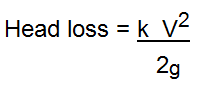
As a comparison lets work out the head loss by both methods. The minor loss coefficient method, and the Equivalent length method. The formula for the minor loss coefficient method is,
Where:-
head loss is in metres (or feet)
k = head loss factor (minor loss coefficient) for fittings and valves.
V = Velocity in metres/sec (or feet/sec)
g = acceleration due to gravity 9.81m/s/s (or 32 feet/s/s)
The important thing is that each fitting is allotted a 'k' value (called head loss coefficient, or minor loss coefficient).
These vary according to the pipe size, however some average values are shown below. For example:-
| FITTING | k value |
|---|---|
| 90deg short radius bend | 1.2 |
| Tee branch (T) | 1.75 |
| Gate Valve fully open(GV) | 0.2 |
| Water Meter | 7 |
Lets say the length to the furthermost fixture in a typical building is about 30m (100 feet), and the pipe is flowing at the maximum allowable velocity of say 2.4m/s (8 ft/sec).
This would equate to a 20mm (3/4") flowing at 0.55 L/s (8.7 gal/min).
Note: The actual internal diameter (ID) of this (copper) pipe is about 17mm. Say we have: 1x7(one water meter) + 2 x 0.2 (Gate valve) + 2 x 1.75 (Tees) + 6 x 1.2 (Bends), giving a total k about 18.
| k | = 7 + 2*0.2 + 2*1.75 + 6*1.2 |
| = 18.1 | |
| Head Loss B&F | = k * (V^2/(2*9.81)) |
| = 18.1*(2.4^2/(2*9.81)) | |
| = 5.3m (52.1 kPa) (7.55 psi) |
Head loss through 30m of 20mm (actual ID is 17mm) @ 2.4m/s, 0.55 L/s = 13m,
(100 ft, 3/4" (0.67" I.D.), V=8 ft/s, Q=8.7 galUS/min, HL = 43 ft)
| Head Loss B&F | = 5.3m (42.6 ft) |
| Head Loss Pipe | = 13m |
| B&F / Pipe Loss | = 5.3/13 |
| = 0.41 | |
| = 41% |
Therefore allowing 50% seems a good figure.
This means that:-
| Total Head Loss | = 5.3 + 13 |
| = 18.3m |
Using the Equivalent Length method
| Total Head Loss | = 1.5 * 13 |
| = 19.5m |
As can be seen, increasing the pipe length by 50% is as good an estimation as any. Bear in mind that everything is an estimation, including the design flow. So no point in splitting hairs at this stage.
In practice however, these head losses will tend to average out, some sections will be over estimated and some pipe sections will be under estimated.
Pipe friction Formulas
There are a lot of standard formulas that calculate flow in pipes eg Manning, Colebrooke white, Darcy, Hazen Williams etc. Friction is accounted for by using a pipe material 'roughness coefficient' in the formulas. However all formulas give a similar result. These programs apply the formula used in the relevant Plumbing Code.
In our situation we start with an 'estimated' flow, we've made a 'best guess' allowance for friction losses in bends and fittings by increasing the length by 50%, Then we normally choose a pipe that is a few mm bigger than necessary, because that is the nearest available size.
Also a large percentage of the pipes will be controlled by velocity (not pressure) more on this below. So no real point in agonizing too much over the formulas, or the head loss, when all the major input parameters can, and do, vary.
However you will find that these programs give the same result as the respective plumbing Codes.
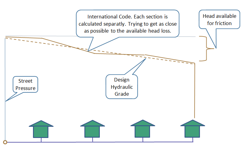
Hydraulic Grade to Furthermost or Highest fixture (Worst case)
As I said, water always flows 'downhill'. The Hydraulic Grade is the slope of that hill. The 'Hydraulic Grade Line' (HGL) is a graphical representation of the hydraulic grade. (refer below) The X-axis represents the length of pipe, and the Y-axis represents the height to which water will rise at all points in the pipe section.
If we draw a vertical line from any point along the pipeline to the Hydraulic Grade Line, the length of this line represents the head/pressure at that point.
The Hydraulic Grade involves only four things:-
- The start Pressure (Street Main)
- The end Pressure (residual head)
- The difference in elevation between the start and end points.
- The length between the start and end points.
Now lets look at the diagram. The available head is what we need to calculate the Hydraulic grade.
The available head is the head that is available for friction losses.
If this head is divided by the 'equivalent' length, we have the hydraulic grade that can be used in our pipe flow formulas.
The steeper the grade the more flow in the pipe. Knowing the Hydraulic grade, and the design flow, we use the Code formula (or any pipe flow formula) to calculate the water pipe size.
Plumbing Code formulas are usually some variant of the 'Hazen Williams' formula.
Note: in real life the hydraulic grade is not a straight line unless the pipe is straight, and the size or flow do not change along the length of the pipeline.
Any head loss as in bends and fittings, will introduce a vertical drop in the line, and changes in size or flow will change the grade of the line.
Smaller pipes or larger flows require a steeper grade, as there is more friction loss.
Conversely larger pipes and/or less flow make the line flatter.
Pipes
Pipes come in many different materials, diameters, and strength grades. To make life easier, pipes are given a 'nominal' diameter. So a 1 inch (25mm) pipe in copper will actually have a different inside diameter for all strength grades, a 1 inch pipe in plastic will have a different diameter again for all the different types of plastic and strength grades. But they are all refereed to as a 1 inch or 25mm dia pipe when purchasing. Sometimes you will see this expressed as DN (diameter nominal).
Pipe flow formulas only relate to the inside diameter (ID).
So the pipe sizing programs on this site calculate the actual inside diameter, and if this exact size does not exist, then for the Australian Programs the next larger available size is chosen. The nominal diameter associated with this size is then displayed.
The international versions display the actual inside pipe diameter (I.D.)
The user can then select the nearest available (larger) pipe size from the Manufacturers data of the material and strength class of choice.
Maximum Allowable Velocity
The worlds Major Plumbing codes set a limit to the maximum water velocity in a pipe.
There are three reasons for setting the maximum allowable velocity.
- To reduce piping noise
- To reduce ware and tare on fittings
- To reduce water hammer.
The Proversions allow the user to enter any value. It is not recommended to increase the velocity above 3m/s. However sometimes it may be advantageous. For example underground pipes of straight runs with no bends or fittings, especially valves. Hence it may be justified in irrigation, fire flows, etc, or even in areas of high pressure when the dwelling is a long way from the source.
But this will be outside the plumbing codes.
Lowering the velocity on the other hand, would be advantageous.
Lowering the allowable velocity requires a larger pipe to get the same flow. Increasing the allowable velocity reduces the pipe size.
So how does this work in practice? The maximum velocity limitation occurs when the available water pressure is high enough to push the design flow of water at a high velocity through a small pipe, and still satisfy the residual pressure requirement at the far end. So to slow the velocity down to the required maximum, the pipe size must be increased. (A bigger pipe carries the same flow at a slower rate.)
As friction loss is dependent on velocity, the friction loss is also reduced. So we have increased the pipe size bigger than what is theoretically required, thereby reducing the friction loss. If we don't loose as much friction as we originally allowed for, we end up with more pressure at the worst case than we originally allowed for. Which can only be a good thing. Some Codes, to be strictly correct, will compensate for this somewhere else in the piping system.
The difficult and laborious way to size pipelines is to progressively calculate the head loss in every individual pipe.
The object is to adjust all the friction/head loss in each pipe section so that the total head loss is as close as possible to the 'available head loss' as shown in the diagram above.
This is necessary in systems where the end pressure must fall within certain limits, as in fire systems, and is recommended in certain plumbing codes. Usually involves a lot of trial and error.
Is it necessary to recalculate the start pressure at the riser for every level of a high rise building?
And will this change the pipe sizes on each level, even if the Architecture is identical?
And is it even worth thinking about?
Well, the lower levels usually have so much pressure that the pipe size is velocity controlled, so recalculating the start pressure will not effect the pipe size anyway. Also during construction it is always better to keep things consistent. Every floor plumbed the same. Easier and quicker to estimate and build, and less chance of mistakes during construction.
Code Differences
Now that we know a few things we can check out the differences in the Worlds major Plumbing Codes.
The Australian Code has a 'Probable Simultaneous flow' of approximately half that of the International Plumbing Code, the British Code BS6700, and the Uniform Plumbing Code (USA).
Does this mean that the Aussies don't shower as much as the rest of the world? or do they have more flow restricting devices?
The Brits however have now introduced a new code BS EN 806 which supersedes BS 6700. This code now beats the Aussi code in that the probable simultaneous design flow is even less. Testing of actual flows are less again.
Well lets take a closer look.
To compare apples with apples I have used a typical residence of:-
1 Kitchen consisting of sink, and dishwasher.
2 Bathrooms consisting of shower, toilet and hand basin
1 laundry consisting of washing machine, and tub.
and one garden hose.
The International Plumbing Code allows grouping of bathroom fixtures. That is, the total loading units of the group is less than the sum of the individual fixtures. This substantially reduces the total loading units, and puts it exactly in line with the old British Standard BS 6700.
The Aussie Code has a one size fits all approach, which significantly reduces the design time, but produces a larger pipe size. However the end result may be similar.
Lets see how this works:-
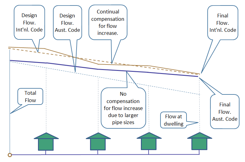
Australian Plumbing Code
All pipe lines in the project are sized to the same hydraulic grade. That is, the hydraulic grade to the worst case. The end flow capacity increases because pipes are not manufactured in the exact calculated size, and a pipe size larger than the theoretical is required. The end flow capacity also increases if the maximum velocity limitation has required a larger pipe size. This increase in capacity is not compensated for elsewhere in the pipe design.
However, for the other codes, there is a larger flow requirement, but also constant manipulation of the pipe size to follow as closely as possible to the design flow.
Below is an attempt to demonstrate graphically how this works.
This diagram is not strictly correct, but drawn this way only to demonstrate the point.
International Plumbing Code
The hydraulic grade is recalculated for each section to try and finish as close as possible to the required end pressure.
If we want to do things the hard way we count all the bends and fittings, and all the other head losses, then calculate the head loss in each pipe section, sum all the head losses and try to make this figure as close as possible to the 'available' head loss.
This is fine, but all the head losses are dependent on the flow velocity, which is dependent on the pipe size. WHICH IS WHAT WE ARE TRYING TO FIND OUT!
So we start with a guess of the pipe size for each pipe section, and then use trial and error to end up with a total head loss, that is as close as possible to what is available for friction.
The end result is, we may or may not have succeeded in reducing a couple of pipe sizes. But are we any more correct? Given that it is impossible to accurately predict the number of bends and fittings the plumber will use, and the 'design' flow may or may not occur.
Is there such a thing as over design in plumbing, (or is it just a better design) if increasing the pipe size reduces the pressure fluctuations?
The free International version of these programs uses the simple approach.
Pro Version
The Australian Proversion will calculate pipe sizes up to 200mm.
The Pro-versions allow the user to input the number of individual fixtures. Also allows the user to input known flows and loading/fixture units.
The Proversion allows the user to change the maximum allowable velocity. This is useful for some other plumbing standards, or for heated water, or for some 5 star hotels that specify different velocities for different locations in the building.
Also allows the user to change the minimum residual head. Handy for tanks (lower residual head), fire hose reels or hydrants (higher residual head), or other fixtures where the manufacturer requires a different minimum head for proper operation eg mixing valves.
The Australian Proversion also has a table that displays the capability of every pipe size, for the calculated Hydraulic Grade.
That is :-
- How many dwellings each size can service.
- What flow (L/s) each diameter can supply.
- And what is the velocity in each pipe diameter.
- And how many Loading Units each pipe can handle.
For example, it might show that a DN25 copper tube can adequately service 3 dwellings, and the next size up (32dia) can service 8 dwellings. So no need to calculate the pipe size for all the dwellings from 3 to 8, as the answer will be 32mm dia.
Also, showing the flow capacity of each size will help in cases where the flow is known. For example, irrigation, some fire services, and some mechanical systems.
If the velocity shown is the maximum allowable, then we know that velocity is controlling the pipe size, not the pressure.
Which means that we have plenty of pressure, which in-turn suggests that we should end up with more pressure at the end point than our desired minimum.
Pumps
Pro version also calculates Pump Duty. This is the required operating point of the pump. It is the flow required, and the pressure required at that flow.
If the hydraulic grade falls below 1:33 then a pump size is calculated. With this hydraulic grade a single residence will require around a DN32 (1.25 inch) pipe. So better to put on a small pump. This is also useful when pumping from tanks etc where the start pressure is zero, or it could be less than zero (less than atmospheric) if the pump is above the tank.
The user can also change this hydraulic grade to change pipe sizes and pump head.
However if the pump is above the tank water level, the program limits the start pressure able to be entered to -60kPa ( negative 6m). Centrifugal pumps will be struggling to suck that high.
However to allow for the head loss of valves, bends and fittings etc, it may be advisable to limit the suction height to about 3m.
When sucking with a pump, is is also necessary to check the NPSH (net positive suction head) of the pump with the Manufacturer. For instance, atmospheric pressure is about 10m (approx 100kPa) (34 feet), but this is already allowed for on our pressure gauge when it reads zero.
So when we read the pressure in a water main, we are reading the pressure above atmospheric.
If we put a pressure gauge on a vacuum it would read -10m (approx -100kPa).
However when sucking, the pump needs to know the pressure above a vacuum. That is the NPSH.
So if a vacuum is -10m and we are only sucking -6m of that, the remainder is 10-6 = 4m. This is the NPSH.
For the phone version, When the pump duty is calculated, use the pump kPa (or start) pressure, (shown at the end of the page) as the 'Start pressure' to calculate the pipe sizes.
For the PC version this is automatic, and the pump calculations are more detailed.
The pump 'duty' point is not the figure that the local pump suppliers usually quote. The suppliers normally quote the maximum pressure that the pump can supply (at no flow). The Duty Point is the required pump pressure when the pump is operating at the 'design' flow. For centrifugal pumps (which is mainly what is used in plumbing situations) the pressure falls off with increasing flow. However somewhere in the system the manufacturer, or pump supplier, will have a 'Pump Curve' that shows pump pressure associated will all flows the pump can produce. Check that out to get the correct pump.